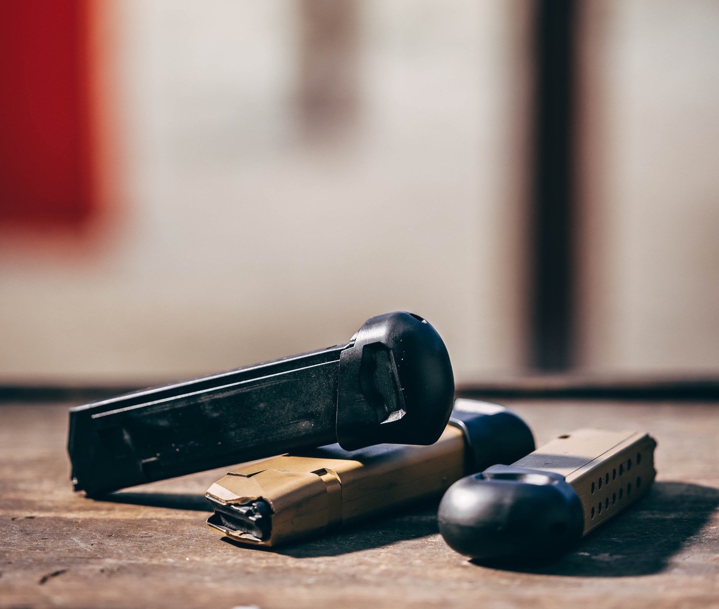
Installation Instructions
This video (Video 1) demonstrates the quick installation procedure. Please view our other video (Video 2) for a more detailed version of the Installation process, the Disassembly process, or the Adjustment of the 3-Pin Locking Bridge.
Installation of the Grip Force EBP
Always wear safety glasses and verify that the magazine is unloaded and clear. The Glock magazine’s internal parts are under tension and may cause injury if not controlled during magazine disassembly.
Tools Needed: safety glasses and a Glock tool or equivalent size pin punch.
The Grip Force EBP is designed only for use on OEM Glock magazines. It will not work on limited-capacity 10-round magazines or aftermarket, non-OEM magazines. Do not attempt to modify the EBP for any magazine other than what brand/model it is intended for.
Remove the floor plate, magazine insert, magazine spring, and follower from the OEM stock magazine. The internal parts are under compression, be sure to keep the bottom of the magazine pointed away from you. When removing the floor plate, control these parts with your thumb by covering the opening as you slide the floor plate off. Remove the OEM follower and install it onto the Grip Force EBP extended magazine spring. It should snap in place. Install the extended magazine spring and follower into the magazine body. Ensure the follower is pointed forward and aligned with the magazine feed lips.
Turn the magazine upside down and hold it with both hands so the front wall faces the left, the rear wall faces the right, and the spring points up. To install the EBP, you must manipulate the magazine spring in the following manner. *Do not bend it to the point where it causes a permanent crease in the spring wire. *A demonstration of this installation technique can be seen on our website videos.
Slide the internal cavity of the EBP part over the bottom of the magazine spring. Compress the magazine spring down using the EBP part and use the index finger of the right hand to push the third spring coil (from the bottom) down into the magazine body. Then pull it back to the rear wall.
Push down on the magazine spring and rotate the EBP part and the bottom two coils of the magazine spring to the left. As that happens, the right index finger pins the third coil (from the bottom of the spring) to the right, up against the inside rear wall of the magazine body. As you compress the magazine spring down and rotate the EBP part toward the front of the magazine body (to the left), the second coil (from the bottom of the magazine spring) also rotates to the left and then down. As it moves toward the front of the magazine, it will dip down into the magazine body while you manipulate the spring. That action is needed to put the slot channels of the EBP low enough to slide onto the lower lips of the magazine’s body. When they are properly aligned, start to slide the EBP onto the magazine lips.
Once the slot channels have started to slide on, hold the EBP and magazine body in that position and remove your right index finger from the inside of the magazine body. Continue to hold both the EBP and magazine body. Finish sliding the EBP onto the magazine, past the side locking tabs on the lower area of the magazine body. The magazine spring will return to alignment once the EBP slides completely onto the magazine body. That action will cause the spring and EBP to create a distinct sound when completed.
Install the 3-Pin Bridge Locking Piece: align the locking piece so the top of the angled cross brace faces inward toward the magazine body’s rear wall. Install the three pin legs down into their corresponding holes on the rear shelf of the EBP. Once correctly aligned, push straight down so the locking piece sits into the holes. Ensure the locking piece is fully seated on the rear shelf; if the friction fit is very tight (that is its design). After pushing the locking piece as low as possible, check to see if there is still a gap between the top of the rear shelf of the EBP and the underside of the angled cross brace. If the locking piece cannot be seated by hand, turn the magazine upside down so the curved bottom of the EBP is facing upwards. Use a flat 90-degree edge of a table or some other object and place the angled cross brace of the 3-Pin Bridge down flat on the top surface of the table/object. Hold the magazine body with one hand, and be sure the top cross brace remains flat on the surface of where it rests. Once stabilized in that position, use your other hand’s palm to strike the curved underside of the EBP part (which is facing upward). That will fully seat the 3-Pin Bridge down into the rear shelf of the EBP. Be sure to function-check the magazine to verify that everything is working.
Disassembly: use a Glock tool through the hole on the underside of the EBP to tap the 3-Pin Bridge locking piece out. Then reverse the assembly procedure. Compress the side walls and locking tabs of the magazine body inward, then slide the EBP part off the magazine body/lips. When you remove the EBP, the magazine spring will bend forward. Slowly release the tension on it.
This video includes the detailed Installation process, the Disassembly process, and the Adjustment of the 3-Pin Locking Bridge piece.
Segments:
0:00 - 6:10 Detailed Installation Instructions
6:10 - 9:10 Disassembly
9:10 - 13:14 Adjustment of the 3-Pin Locking Bridge
